
The above is a photo of a 70’s style fuzz distortion pedal I put together. It is the most simple circuit I found on the web for a “diy” distortion pedal; there are many more circuits that are very complicated compared to this one. It sounds great. I figured out how to add an led as well as switching for bypass, which means I can play with it plugged in and choose between having fuzz distortion or not. It is a “Bazz Fuss” pedal.
Of the three switches, one connects the two jacks together and the other two turn on/off the 9v power supply (one on “+” and one on “-“). The knob is for volume. I did not add a tone knob, because tone knobs on other pedals I have experimented with did not change the sound enough to further complicate the circuit. I realize I currently have minimal knowledge of electronic circuits; I am a beginner with these notions. The three wires in the photo are the 9v wire and two 1/4” cables, one to the guitar (in) and the other to the amp (out).
Here are two video links to see how this same kind of pedal is made: fuzz1 fuzz2. To make your own fuzz pedal, watch these videos to draw out the circuit and write down the components. You may want to check out mammoth for components if you are interested in making a pedal. A very large selection of components can be found from mouser. For dozens of awesome “diy” pedal kit options/circuits, check out guitarpcb. There is even a Pink Floyd jet pedal on that site. For the best price on an excellent temperature controlled soldering station, I suggest this one. Mine works great and heats to 300 degrees in under thirty seconds (just like it says on the box). The last three soldering irons I have used and owned do not even compare to the above mentioned soldering station, and one can even order replacement tips for it. I like the tip that looks like a cone. There are also many pedal kits, even if more common, on Amazon.
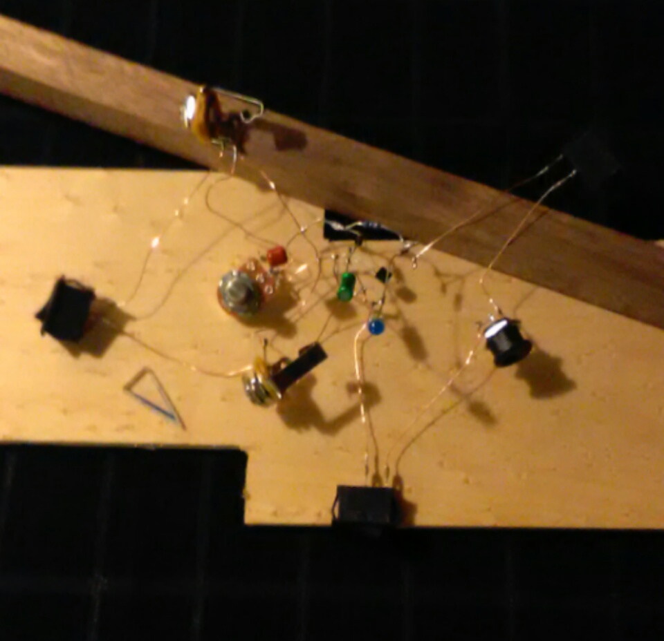
Below is the circuit I put together and tested before deciding whether I would put it in an enclosure. I found the 1/4″ jacks for the guitar cables on Amazon.

Obviously, one would not want to build an enclosure for a circuit that does not work. This was the third circuit I tried to make for a distortion pedal and the first one that worked. I may solder together a more complicated one eventually; however, for now, I plan to spend some time with my writing and learning to play the guitar better.
If you watched the videos and looked up “fuzz pedal circuits” on bing, you will notice that the circuit above utilizes a 9v power supply. I added the three switches on my own, as well as the blue led and 470 ohm resistor. First, I added the one (switch) that connects the two jacks’ negatives, for bypass. It only worked when I unplugged the power supply, so I added the other two switches in order to be able to have it plugged in and also off, to play without distortion.
As it is, I can turn the two 9v switches on and the jack connection off to play with fuzz distortion, and turn the switches the opposite for ‘near’ true bypass (it is hard to notice any distortion when it is configured for bypass).
The circuit above may look all sprawled out. It was, and I figured out how to get the led and bypass working (which took about a week due to the small amount of time I put into it, daily) before I chose to clip the wires and shorten/bend them and re-solder the circuit. It would need to be smaller to fit into a box. I played with it; it worked; I was happy; and I decided it was good enough for a halfway descent wooden enclosure. I chose a triangular box structure idea with a light in the middle of it. It would have walnut corners and birdseye maple sides, top, and bottom.
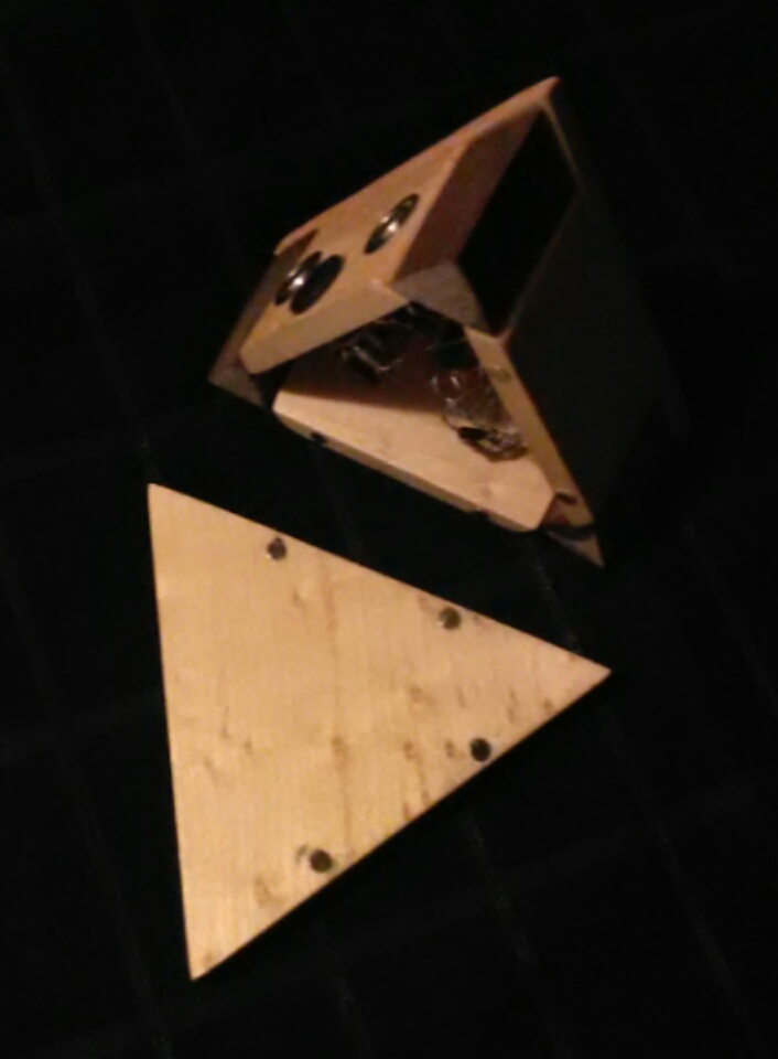
The photo above is of the wood before I sawed it out, as well as the circuit as it was before I made it smaller. The isosceles triangle in the photo is the piece of Plexiglas I sawed out for the light. The led is bright, and the triangle does a fine job of both adding some to the looks of the box as well as dimming the light just enough.
When I bent/clipped the wiring and de-soldered certain connections in order for it to fit correctly in the enclosure, I accidentally soldered it back together wrong. It did not work, and it was not encouraging. I took a break from it for a while and then checked the circuit diagram I drew from the videos on YouTube. I found the problem and re-soldered the connection, and it worked. I used solder from RadioShack, the kind that is shiny.
For the record, the components I used are not exactly the same as in the videos. They are close enough; it works. I would suggest getting the exact components mentioned in the videos; anything else besides those may or may not work. Some components are interchangeable and some are not. The resistor is; I decided to go with a 100k resistor (the one for the circuit, not the extra one on the led) instead of a 10k, because the 10k kept giving out halfway through guitar notes. In order for it to work the best, I keep the guitar and the pedal turned up all the way, and the amp’s volume turned down to 2.2 or so. It is, as they said in the videos, a very loud pedal. It is best to have the volume all the way down on the amp when you first plug in the pedal.
 The above photo is of the enclosure and the circuit. During the time of this photo, the circuit was not working; I did not have the bypass switches wired the right way, yet. Of course one could more easily add a bypass to this circuit with toggle switches; however, I did not have any and was anxious to complete the project. Here is a link to those wonderfully nostalgic power supply switches. Here is one for toggles. The copper wire I used is 24 gauge and I found it on Amazon. It can pick up radio wave interference without the enclosure, and does, so I recommend using red and black insulated wire instead.
The wood did not take me too long to saw out and sand, and I used clearcoat polyurethane on it instead of a stabilization process.
Here is a photo of the circuit after I got it working again.
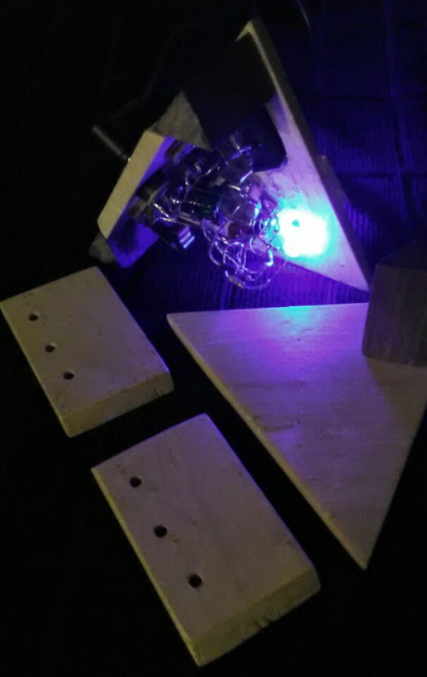 You can see that the light is on. I used a liquid wood filler to correct the holes I drilled into the top of it for the 9v switches. In my design, I did not make enough room for the potentiometer and the switches, so I had to redo how I had it originally drawn. I was happy that it worked again and plan to practice chords and scales with it.
Here is a photo of the enclosure after I got the neodymium rare-earth magnets in it.
 The magnets are not installed to perfection; however, they are close to it. I am impressed with the luck I had in getting them at least as close to perfectly placed as I did. I used a piece of paper to make a stencil to get them lined up right, and drilled their holes and fit them with superglue.
Was the project over? After days and days of working on it in the afternoons? No. The circuit worked great; it did everything I wanted it to do. The bottom of the enclosure fit great to the rest of the pedal. So what could have ‘possibly’ been wrong with the final project? The jacks. They bumped up against the side of the triangular box, so the cables would not connect properly when inserted. I solved the problem with a whittling tool, which means there is an extra hole in one side of the enclosure. Does it really matter? Not really, because it works great and does not really look too bad.
The tiny holes in the sides of it are for heat-release. The circuit does not really get too hot, yet I figured it a descent notion to not seal it air tight. Light does not really come out of those little holes. Even though the box is made of wood and is highly flammable, I do not intend on having it on and plugged in for a long time. If it starts smoking, I’ll unplug it. If it starts a fire, I will put it out with an extinguisher or a large wet towel. I’ve already played with it for over an hour; the circuit does not really get hot. I do recommend aluminum enclosures for building pedals; many kits come with those kinds of enclosures.
So, that is my fuzz pedal. I have spent the last few months revising my first collection of stories for a second edition of “Acoloftals”. The new edition is highly similar to the first one and includes a complete revision of this story; I made at least thirty necessary changes to the text and have revised it entirely twice, so far. That is what kept me from putting more stories on my blog, time-wise. Once it is done, I plan to write a screenplay. Here is the photo of the pedal in its distortion setting, one more time. It sounds just like the pedals in the videos. Total hard metal.
Thank you for visiting jcm3blog and have a nice day.
♦
